2 Plan Layout The total power supply capacity of substation is decided from load survey of that area with consideration of future expansion. Silicon Engineering caters to all your.

Layout Of 220 Kv Substation Download Scientific Diagram
Communication System Layout Diagram 52 Figure 35.
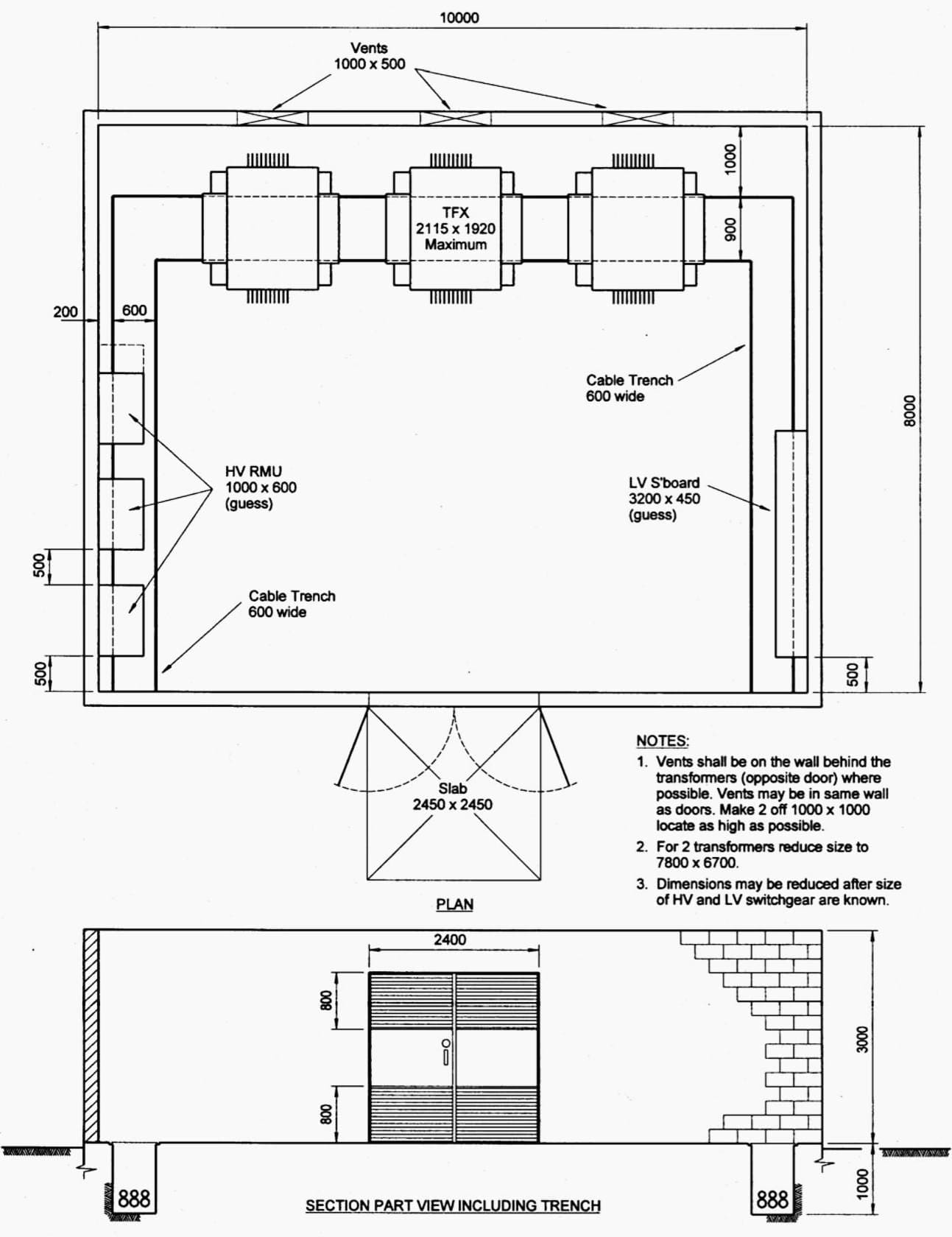
. There is numerous electrical substation components like outgoing and incoming circuitry each of which having its circuit breakers isolators transformers and busbar system etc for the smooth functioning of the. Electrical Symbols Electrical Diagram Symbols How To use House. 33kV TT 11kV Figure 1.
An Electrical Substation is an essential part of the above mentioned process. Layout 1 Also showing Proposed Access Road. Draw the layout diagram of external substation Velvet manicure can make the nails produced as if of velvet and they seem quite comfortable to the touch.
Five 100MW 11kV 3F Y connected 50Hz ii Step-up transformers. All relays and other major. Incoming or power feeder connection 33kv Incoming Line Power transformer connection via Lighting Arrestor.
Water sewer gas and telecommunications. Two 5MVA 11kV400VDY3F50 Hz Show. A single-line operating diagram gives a simplified schematic circuit diagram of the substation.
Five 100MVA 11220kVDY3F50Hz iii Bus. Or mimics the actual bus layout in the substation. Substation Panel Diagrams REMOVED FROM SCOPE 102013 The senior design ream will be required to create a panel layout and schematic diagram to be furnished to a panel vendor.
An analogous effect is realized by a Exclusive. 1 Single Line Diagram Fig. The single line diagram makes the system easy and it provides the facilitates reading of the electrical supply.
The vendor will use these materials to generate a wiring diagram. Substation provides the energy supply for the local area in which the line is located. Electrical Substation Now days the electrical power demand is increasing very rapidly.
Draw the layout diagram of external substation Ditulis steffensmeier Kamis 24 Maret 2022 Tulis Komentar Edit Use Lucidchart to visualize ideas make charts diagrams more. 220kV-Double bus with a bus coupler iv Outgoing lines. Problem 1 Draw the Single Line Diagram of a generating substation having the following main equipments.
Indicative Substation Layouts Diagrams Appendix Q to the Response submitted for Deadline I Application Reference. The IC layout diagram or IC mask layout refers to the internal design of a semiconductor component. Preparation of Layouts like Cable Tray route design Earthing Layout Lighting Layout Main equipment Layout and Floor slab opening details.
Consider a 33kV11kV transformer TR1 which supplies substation A as illustrated in Figure 1. Create diagrams all while collaborating in real-time with your team. The substation is the part of an electrical supply system which transmits the high voltage from the generating substations to the local distribution networks.
Substation Equipment Layout Regional cable head-end diagram Draw Diagram Software Basic. The Substation Equipment Control Building Rigid Bus Structures And The Perimeter Fence. Between the generation and distribution the voltage may vary through several substations.
Therefore to avoid this difficulty lightening arresters are. Single Line Diagram of an Electrical Substation. The different types of layout for substation are explained below in details.
It is made up of multiple layers or masks of metal oxide and semiconductor material to form an Integrated circuit IC. Substation A simplified diagram The transformer parameters are as follows. Designing a New Power Substation.
Figure 5 - Landscape Plan with Indicative 900 MW HVAC Substation 900 MW HVDC Converter Station Layout 2 Also showing Proposed Access Road. Once the substation planning has been completed with real estate acquired and the project has kicked off. The Physical Design Will Be Shown On A Plan View Drawing Which Will Include The Locations Of The Following.
Figure 1 Typical single line diagram of a 1104 kV outdoor substation click to expand The 3-phase 3-wire 11 kV line is tapped and brought to the gang operating switch installed near the substation. Five 220kV v Station auxiliary transformers. Substation decided it is necessary to draw a Single Line Diagram also called Key Diagram.
Switch consists of isolators connected in each phase of the 3-phase line. Power may flow through several Electrical Substations in its journey from the generating plant to the final consumer. Instead Of Being Owned By The Power Utility If The Distribution Substation Is A Direct Supply From The Transmission Entity To The Customersubstations Can.
Draw The Layout Diagram Of External Substation. EN010053 15 July 2015. The substation equipments such as conductors transformers etc are always erected outdoor.
The team will also be responsible for generating wiring diagrams for the yard equipment. The gang operated switch GO. Integration of microprocessor relays and the internal logic and external communication configurations and present approaches to deal with these issues.
The connection of the substation is divided as. The word Substation was more commonly used in the past when the distribution system was not in a grid Layout. Sn 22 MVA V 33 kV Vi 11 kV Connection group Dy7 On load tap changer on HV side operating in 10 range.
Voltage transformer connection for control and metering. Whenever light surges occur then a high-voltage pass through these electrical components causing damage to them either temporary or permanent damage based on the amount of voltage surge. Depending upon the availability of resources these stations are constructed.
The single line diagram of the 33kv substation is depicted in the figure below. Figure shows the civil structure layout of substation. The main function of the substation is to receive the energy transmitted at high voltage from the generating station and then reduce the voltage to an appropriate value for local.
Ad Use Lucidchart to visualize ideas make charts diagrams more. Layout The first step in planning a substation layout is the preparation of a one-line diagram which shows in simplified form the switching and protection arrangement required as well as the incoming supply lines and outgoing feeders or transmission lines. These power generating stations may be hydro-electric thermal or atomic.
A scaled site plan will be created to determine the right of way ROW access for roads transmission lines distribution lines and other utility access such as. Microwave Radio Communication System Diagram 54. One-line diagram should include principal elements.
The electricity substation is a network of electrical equipment which is connected in a structured way in order to supply electricity to end consumers. It represents the geometry as well as the size of different semiconductor layer and their connection. For fulfilling these huge power demands the modern time requires creation of bigger and bigger power generating stations.
Lines Switches Circuit breakers Transformers.
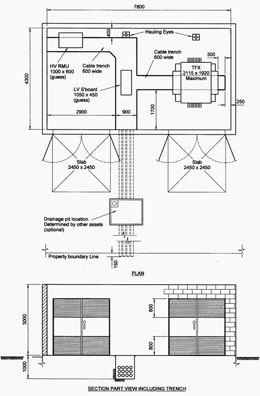
7 Typical Layout Designs Of 11kv Indoor Distribution Substation Eep
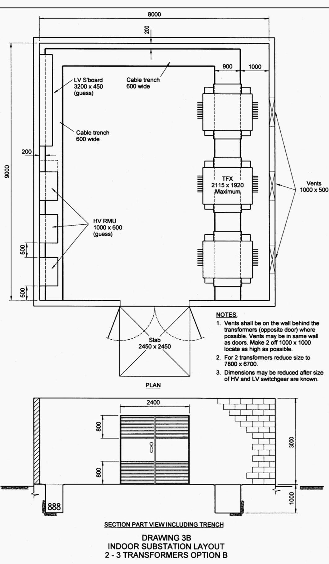
7 Typical Layout Designs Of 11kv Indoor Distribution Substation Eep

7 Typical Layout Designs Of 11kv Indoor Distribution Substation Eep
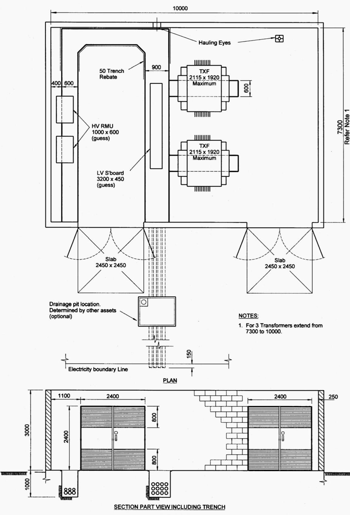
7 Typical Layout Designs Of 11kv Indoor Distribution Substation Eep
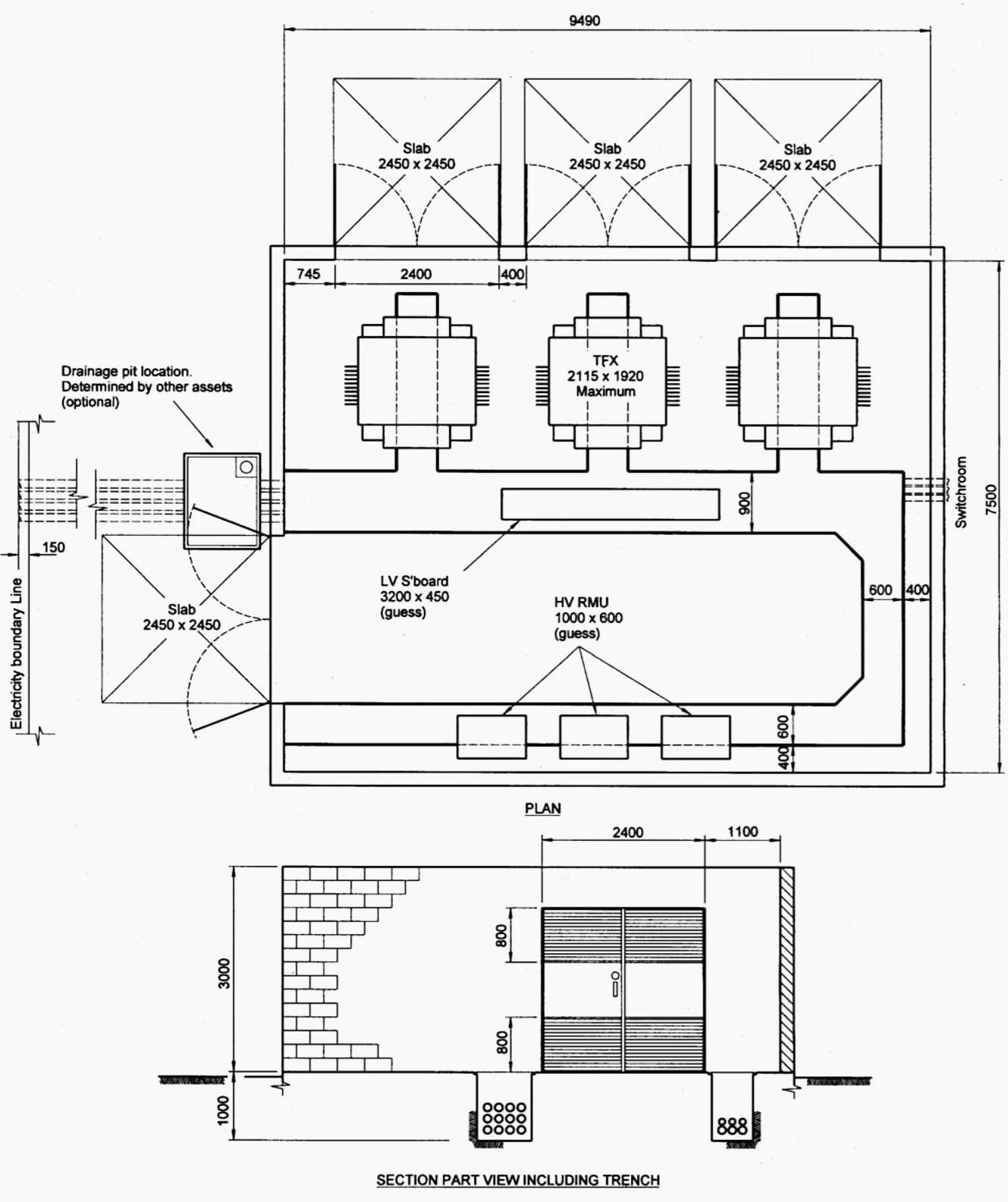
7 Typical Layout Designs Of 11kv Indoor Distribution Substation Eep

9 Layout Of Cern S Standard 66 18 Kv Substation Download Scientific Diagram

Plan Of The 1000 Kv Uhv Substation With The Measurement Positions Download Scientific Diagram
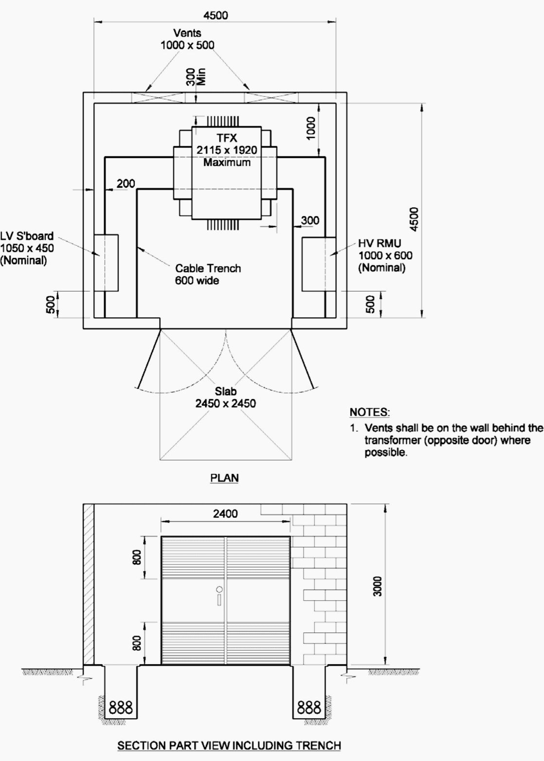
7 Typical Layout Designs Of 11kv Indoor Distribution Substation Eep
0 komentar
Posting Komentar